The Pen class has a few advanced members such as:
There are also a couple of related classes such as CustomLineCap and AdjustableArrowCap.
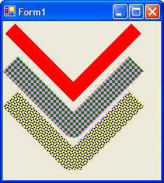
A SolidBrush is one where the whole width of the Brush stroke is a single solid color. A TextureBrush is one where the fill of the Brush consists of a bitmap. The HatchBrush is one that is made up of repeating patterns. The LineJoin demo illustrates the LineJoin member as well as using a HatchBrush.
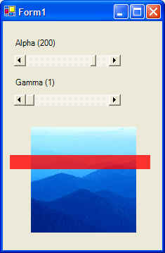
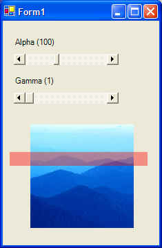
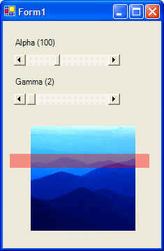
GDI+ offers two types of blending:
To use alpha blending you will need to be familiar with the following terms:
The Graphics.CompositingMode enumerations is
used as a switch to turn of/off the transparency of the source image or
color.
The following project Blending show the effect of setting various values for Alpha and Gamma factors:

Usually the simplest way to force the form to repaint itself is by calling the form's Refresh() method. Most other controls also have the Refresh() method. However, there is a problem with calling the Refresh() method every time you need to show something new on the form: calling the form's Refresh() method forces a repaint of everything on the form. If you have a complex form with many painted shapes, calling the Refresh() method to update only a small area of the form is a waste of time since everything will be repainted. More importantly, this quite often results in flicker.
The question is: how do you repaint only the area of the form that needs it? Invalidate only the area (or region) that needs to be repainted.
There is an Invalidate method for every control, including the form. This method has many overloads as shown below:
Note that invalidating a region is the finest control you can have in deciding which part of the form to repaint. Recall that a region can consist of a graphics path, which itself can be of any shape you can think of. If you like, you can invalidate a region of the screen shaped like an octagon, a heart, a letter, or any other shape you can think of.
Suppose you had a form with all kinds of shapes on it and you wanted to change the fill color of one of those shapes. Here the important steps to repaint just that shape. Note that this is just one way to accomplish this goal:
These steps result in everything inside the rectangle to be redrawn while the rest of the form is left alone. Note that while this method of redrawing controls goes a long way in reducing flicker, there is more that can be done to smooth out the drawing process.
The ControlStyles enumeration is a set of bit fields whose bitwise combination defines how the screen is painted. Bits can be individually be set/get using SetStyle / GetStyle methods. The following members of ControlStyles have to do with painting:
| Name | Description |
| AllPaintingInWmPaint | WM_ERASEBKGND message is ignored to reduce flicker. If this bit is set, the control's OnPaint and OnPaintBackground are called directly from the WM_PAINT message. |
| CacheText | Control keeps a copy of text instead of getting it from the text handle. |
| DoubleBuffer | Drawing is done in the background buffer and then blasted to the foreground. This is probably the best way to reduce flicker. To fully enable double buffering, you must set AllPaintingInWmPaint, DoubleBuffer, and UserPaint bits. |
| Opaque | Control is drawn opaque. Background is not redrawn. |
| ResizeRedraw | Control is redrawn when it is resized. |
| SupportsTransparentBackColor | Control accepts a background color whose alpha is less then 255. |
| UserPaint | Control paints itself rather then the operating system. |
There is one last thing you can do to help reduce flicker. Suppose you needed to change the background color based on some user preference. You can do this using the OnPaintBackground method to paint just the background without touching the foreground. Note that this method does not reflect a real event since there is no PaintBacground event. So you how do you invoke this method? Call the control's InvokePaintBackground().
An example of reducing flicker using the above methods is given in an example in the following section.
The true power of blending is where you start filling a shape with a particular color and ending the fill with another color. The two classes that deal with color blends are:
And the two classes that use the above blend objects are:
LinearGradientBursh is a brush that has a start color and an end color. It also has a repeat pattern defined by a start point and an end point on the screen. The linear gradient part of the brush means that the color is interpolated linearly between the start color and the end color along the length of the repeat pattern. The repeat pattern is defined for the whole graphics container. That means if you made a brush that starts blue at (0,0) and ends up red at (100,100) and you start drawing at (50,50), then the first color of the rectangle will be some shade of purple (in-between blue and red). This is because you started at the point where the brush was changing from blue to red.
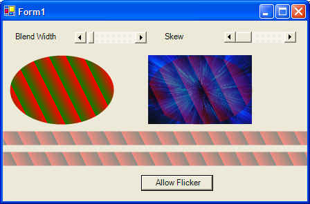
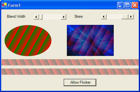
The Blend And Flicker project shows blending and flicker elimination concepts in use. Below is a sample output:
Whereas the LinearGradientBrush start with one color at the start point and ends with another color at the end point, PathGradientBrush starts out with a color at the center of the path and ends with another color at the outer edge of the path. The classic example is comparing a line that starts green and ends blue to a circle whose center is green and ends in blue. Both kind of brushes can have an unlimited number of colors between the start and end colors.
Path gradient brushes often take a WrapMode argument which tells the drawing method how a gradient is to be tiled when the object lies outside the gradient area. Project Path Gradient illustrates how to use a path gradient brush:
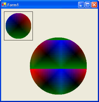
Note that path gradient brushes are used to fill objects from the center on out. This assumes that a PathGradientBrush has intelligence to figure out the centroid of the object it is required to fill (not everything will be a rectangle or an ellipse.) As seen from the Path Gradient demo, setting up a PathGradientBrush object requires more than creating it via constructor arguments. At least, two more properties must be set before you can use a PathGradientBrush object: the center color and the array that leads to the outer color
PathGradientBrush pgb = new PathGradientBrush( gp.PathPoints, WrapMode.TileFlipX );
Color[] c
= { Color.Blue, Color.Red, Color.Green };
pgb.CenterColor = Color.Black;
pgb.SurroundColors = c;
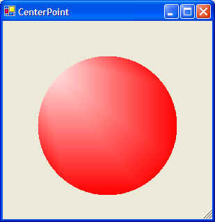
Another interesting property is CenterPoint, which get or sets the center point of the of the path gradient. CenterPoint is calculated by the brush from the path given at construction time. This property can also be set to any value in the world coordinate space. This property can be used to introduce a light effect from any position. Again from Path Gradient:
Transforms rely heavily on a mathematical construct call the Matrix. The following definitions are crucial to working with transforms in GDI+. Also note that transforming a shape means applying the correspondingT mathematical operation to each and every point (x,y) within that shape.
Linear transformation (multiplication) and translation (addition) are the two things you can do to a point in the GDI+ space. The combination of transformation and translation is called affine transformation. It would be nice to able to represent transformation and translation in a single matrix. As expected, GDI+ has the Matrix object which is a 3 x 3 matrix representing an affine transformation. To enable the use of the Matrix object, each point should be saved as a 3 x 1 matrix with a dummy third coordinate equal to 1. The third column of the matrix will always contain the numbers (0, 0, 1)
For example, the point (10,20) would be represented as (10, 20, 1) with 1 being the dummy coordinate. Suppose you wish to rotate this point by 90 degrees and translate it by 7 units in the x-direction and 12 units in the y-direction. The transformation would look something like:
[10 20 1] x 0 1 0
-1 0 0 = [-38, 32 ]
7 12 1
Note an important point: In the previous example, the rotation matrix applies a rotation of 90 degrees with a scaling of 1. This means that the 2 x 2 matrix used to specify rotation is also used to specify scaling in the x- and y-direction.
Often, you will want to make several transformations in a series. For example, you may wish to transform (rotate) a point by 60 degrees, scale it by a factor of 3 in the y-direction, and then translate it 3 units in the x-direction. This sequence of transformations can all be multiplied together to a make a single 3 x 3 matrix and then stored in the Matrix object. Conveniently, the Matrix object has several methods that allow you to perform all these operations and more:
Recall that transformation really means rotating and scaling where as translation means moving in the x- and/or y-direction. TransformVectors is used to specify rotation and scaling at the same time, whereas TransformPoints is used to specify rotation, scaling, and translation. The following list shows some of the classes that use the Matrix object:
In general, the Matrix object is used in the following way: Setup the Matrix object with the required transformations by creating the Matrix object and then applying the required rotation and translation by calling the appropriate methods on the Matrix object. Once the Matrix object is setup, apply the Matrix object to the appropriate GDI+ object. All drawing with that GDI+ object will then reflect the transformations of the Matrix object.
For example, in the Transform Shape project, I setup the Matrix object and then associate the Matrix object with the Graphics object. All drawing with the Graphics object will now reflect the applied transformation. In this project, I allow the user to set rotation and translation values (via the scroll bar) . In OnPaint, I create a new Matrix object that reflects the new values and apply it to the Graphics object. The following shows a rectangle in its default position, then rotation, then translation.
![]()
![]()
![]()
Note that the rectangle is not moved at all. The Matrix object is applied to the Graphics object, and it is the Graphics object that has changed. Similarly, the Matrix object could be applied to a brush and it will be the brush's rectangle that will be affected. We will never change the brush's rectangle coordinates, but it will be the Matrix object that causes the brush's rectangle to be transformed.
What follows in this section are some of the miscellaneous methods and classes that round up this section. They are
GetNearestColor returns a Color structure that is the nearest system color to the color you have specified.
// Create some random color
Color c = Color.FromArgb(100, 120, 120);
// Now get the nearest system color
Color cSystemColor = Graphocs.GetNearestColor( c );
The ColorTranslator class allows you to move from one color definition (Win32, OLE, HTML, etc) to another. This is probably mostly used when you need to interoperate with Win32 and/or COM using .NET Interop
Recall that a GraphicsPath object in general consists of more than one shape. The GraphicsPathIterator shape provides functionality to isolating selected subsets of the path. The GraphicsPathIterator also allows you to trace a path. If you have a GraphicsPath made up of many complex shapes, the GraphicsPathIterator allows you to trace this path and get some information about the path. For example, you can create a GraphicsPath object that is made up of n shapes. Each of these shapes is referred to as a subshape. The GraphicsPathIterator shape call tell you various information about each shape, for example, if the shape is close and what the start and end indexes are.
You can get information about any region you have created by using the RegionData class. This class has one member called Data. It returns an array of bytes describing the given region. You can keep the RegionData object in memory, manipulate its data, and create a region from the object's data.